Stepping into a New Dimension: Using Quaternions to See the Invisible
- Jun 25, 2019
- 6 min read

Our previous project blogs documented some of the advancements we have made in creating an AR-based magnetic field visualizer for personal mobile devices. Since then, we have made some significant advancements, and have released a beta version of Physics Toolbox AR Field Visualizer for Android. (An iOS version is pending, but will likely be posted within the next few weeks).
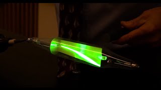
The video hyperlinked to the image below shows the basic functionality of this app, and visualizes the background magnetic field of the Earth. Creating field vectors in open space is significantly more challenging than placing pre-fabricated 3D objects on flat surfaces or at a single point in space, because both the frame of reference (the screen) and the object (the vectors) need to rotate with respect to one another.
This ability to place rotated objects within a rotating frame of reference is a significant technological challenge—one that dates back to almost 50 years ago with Apollo 11.

Scientists, engineers, and mathematicians of all types have been challenged by three dimensional rotation for a long time. Apollo 11’s astronaut Collins was plagued by the mechanical limitations of his capsule’s inertial measurement unit (similar to the much smaller sensors that can be found in smartphones to measure rotation) while he tried to maneuver while in orbit during the first Moon landing (more on this below!).
To develop an app that understands how to display rotated 3D objects in a 3D world, we had to look into a 4th dimension.
For as much as the general public makes light of the word “STEM,” with its fuzzy connotations of somehow mixing together a concoction of many often disparate disciplines, solving the problems associated with making a magnetic field visualizer requires blend of computer science, physics, electrical engineering, and math.
Early in our testing of the app, we realized that the direction of the vectors appeared to switch unexpectedly as we rotated the screen. For example, a background field vector (which should remain static with respect to the ground), would suddenly be displayed in a different direction after rotating the phone. This unexpected switching seemed to occur at key points that often seemed to be at 90 or 180 degrees different from one another. We soon realized that we were experiencing a phenomenon known as “gimbal lock.”
What is a gimbal?
When dealing with systems that rotate in three dimensions, you might envision quantifying that rotation with Euler angles that dip away from the x-, y-, and z-axes. A concrete example of a physical system that is capable of rotating in all three dimensions in space is the MAT, a device that has been popularized to the general public through its exhibition at Space Camp. (See a
video of Rebecca on the MAT at Space Camp). In the case of the MAT, three rotating rings are used. A mechanical device that permits rotation in any plane is known as a gimbal. In the case of the MAT, the carriage and the three rings and their axes serve as gimbals, while in other devices, such as camera bases on tripods, a series of joints might serve the same purpose.
What is gimbal lock?
Gimbal lock occurs when at least two of the axes of rotation end up parallel to one another, effectively decreasing the range of motion by one dimension less than the number of gimbals available. In a mechanical system, three gimbals are necessary to represent 3D motion. In a three-gimbal system, if two gimbals align with one another, motion can effectively only happen in two dimensions without "resetting" the system and moving all three gimbals. The video below describes this limitation.
The practical effect of gimbal lock is not a physical “locking” as in rotation that becomes stuck, but in the inability to represent its motion in a mathematically simple way using Euler angles alone. Astronaut Michael Collins understood this problem in a very real way when he attempted to maneuver his module during his meet-up with the lunar module carrying Neil Armstrong and Buzz Aldrin back from their trek on the Moon. As described in the video below, Collins quickly grew frustrated when it took multiple attempts to manually reset the navigation system using stars after trying to appropriately orient himself and hitting gimbal lock scenarios. According to this NASA transcript and audio recording, at one moment Collins asked Mission Control, "How about sending me a fourth gimbal for Christmas?"
Likewise, when rotations are represented with math in three dimensions, a similar locking can occur. As the mobile device and the respective vector rotate about, there are points at which they approach a mathematical gimbal lock. When a gimbal lock is approached in the visualization of vectors, for example, the resulting data is often chaotic and nonsensical.

How can gimbal lock be overcome?
There is an elegant solution to overcoming both physical and mathematical gimbal lock that are effectively analogous to one another. In the case of Apollo 11’s navigation system, the addition of a fourth gimbal would have prevented Collins’ multiple invalidated attempts in space. So long as the fourth gimbal is maintained out of sync with the other gimbals, the alignment of any two of the three internal gimbals would have decreased the dimensions of freedom from four to three, avoiding the issues Collins encountered. (NASA engineers had considered the use of a fourth gimbal before the mission, but decided it was not necessary for efficiency’s sake. You can check out the official transcript of Collins’ interaction with Mission Control and his Christmas request for a fourth gimbal).
The mathematical solution to gimbal lock is not much different—add another dimension. This particular solution can be resolved by using something called quaternion math. Unlike more traditional vector algebra, which makes use of a vector representation that uses i, j, and k, quaternion representations include the addition of a constant and effectively project 4D information onto a 3D world. The elegant—although lengthy—video below explains how 2D worlds can be projected onto a 1D map, how 3D worlds can be projected on a 2D map, and, lastly, how 4D worlds can be projected onto a 3D map, as is the case with quaternions.
If the video above is a bit too math heavy, here is a simple conceptual model. Envision an orange. Slice the peel from top to bottom and proceed to carefully remove the fruit while maintaining the peel intact. The peel is a shell that takes a 3D form. Then, proceed to open it (allowing to tear where necessary), and flatten it on the table into a 2D representation. The peel no longer looks circular. However, its critical information—the surface area or any patterns on its surface, for example—persist, and its 3D form could be reconstructed with care if desired.

The reduction of a 3D world to a 2D visualization is something that is regularly used by all of us when we construct maps, although the approach to doing so is varied (see the various types of projections below), and there are different affordances to using various types of projections. The point, however, is that it is possible to theoretically represent a 4D world (or, in this case, 4 gimbals) in a 3D world.

By adopting quaternion math and 4D representations for our vectors, we were able to achieve a working magnetic field visualizer. It should be noted, however, that quaternion math is not unknown to software developers, as it is a core aspect of computer-based games. However, the challenge was in linking this information to appropriately filtered environmental sensor data and locking it to a 3D grid through the AR framework. In gaming environments, these data is frequently computer-generated through an idealized algorithm and carefully situated within a similarly computer-generated and controlled environment.
Where does this leave us?
The major achievement of building this app leaves us with pretty functional tool for mapping magnetic fields and visualizing them in 3D space without the concern of gimbal lock. The video below demonstrates changes in magnetic field direction around North and South magnetic poles of a stack of ceramic magnets. We encourage you to try out the app and provide feedback.

Now that the major milestones have been achieved, our next steps are to create calibration tools to off-set the difference between the location of the magnetic field sensor, camera lens, camera display, and the source of the field arrows as they are produced. Our education research team and advisory board are underway to refine a protocol to see how this app might support introductory and advanced physics students’ thinking about fields in general and magnetism in particular. If you would like to be a part of this research project, please reach out to us at support@vieyrasoftware.net.
This work is funded by NSF Grant #1822728. Any opinions, findings, and conclusions or recommendations expressed in this material are those of the author(s) and do not necessarily reflect the views of the National Science Foundation.


That’s a fascinating dive into quaternions — understanding invisible rotations really opens up new ways to approach 3D modeling and gaming physics. It reminded me of how digital assets can now come to life in physical form with 3D printing. If you’re interested in exploring models for printing, a great resource is https://www.gambody.com/premium/star-wars-rogue-one-droid-k-2so which offers STL files from popular video games and comics. Platforms like this bridge the gap between virtual creativity and tangible 3D printing, making it easier for hobbyists to bring digital worlds into their homes.